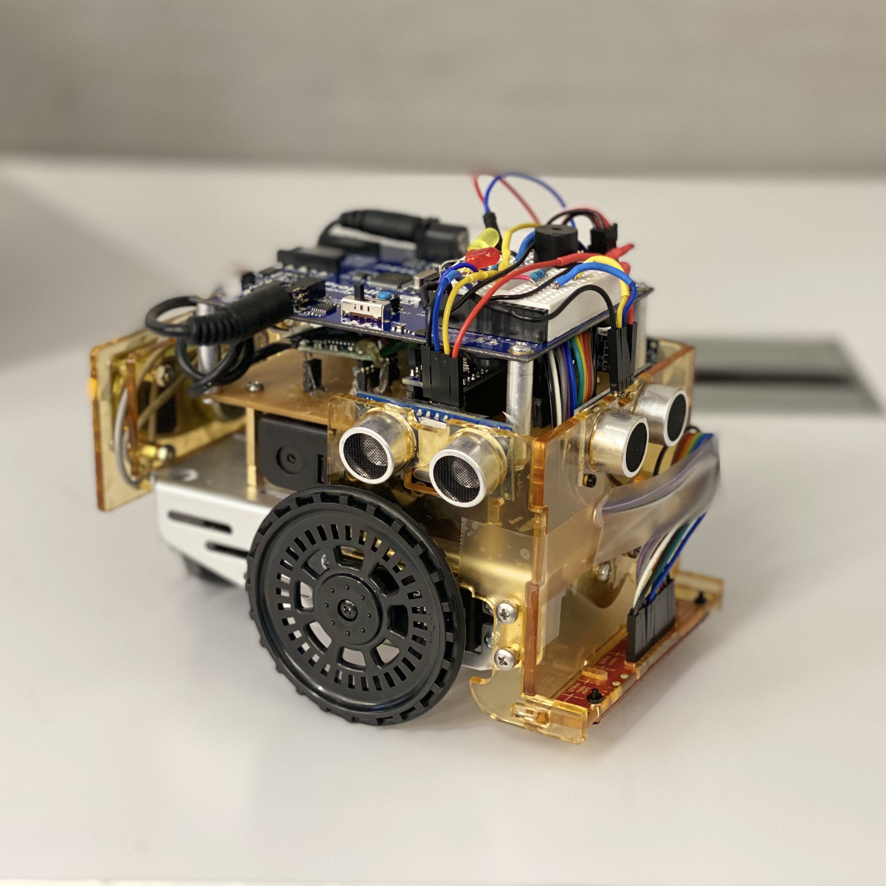
A line-following robot using a Parallax Propeller as the master controller and an Arduino Nano as a slave for QTR sensor reading. The Propeller’s multi-core architecture enables simultaneous line-following, ultrasonic scanning, servo control, and indicator signaling. Built for a contact-less delivery scenario in a grid-like track (Manhattan/Brooklyn street pattern).
Group 19: Dajr Alfred, Gordon Oboh, Mohammed Nauman Shariff
The robot navigates a grid track with 16 intersections (i0–i5, B1–B5, A1–A5), 10 delivery points, and a randomly placed obstacle in the center lane. Using the Propeller’s 8-core COG architecture, all sensing and control tasks run in parallel — no need to stop and scan.
Key upgrade from Arduino-only version: Multi-core processing allows the robot to follow the line, read ultrasonic sensors, control servos, and signal indicators simultaneously.
┌─────────────────┐     UART (115200)     ┌──────────────────────┐
│  Arduino Nano   │ ────────────────────→ │  Parallax Propeller  │
│  (QTR Sensor)   │    sensor data        │  (Master Controller) │
└─────────────────┘                       └──────────────────────┘
                                                   │
                                    ┌──────────────┼──────────────┐
                                    ▼              ▼              ▼
                              Servo Motors   Ultrasonic x3   LEDs + Buzzer
The Arduino reads the QTR-8RC reflectance sensor and sends the data to the Propeller via serial. The Propeller runs 5 concurrent COGs:
| COG | Function |
|---|---|
| Position (ardcog) | Reads QTR data from Arduino via UART |
| Distance (ultcog) | Reads 3x Ping ultrasonic sensors |
| Servo (servocog) | Controls left/right servo speed and direction |
| Line Follower (lfcog) | PID-style error correction for line tracking |
| Buzzer (buzzcog) | Audible indicator signals |
| Component | Details |
|---|---|
| Master | Parallax Propeller Activity Board (P8X32A-Q44, 8 cores, 32KB RAM) |
| Slave | Arduino Nano (QTR sensor interface) |
| Line sensor | Pololu QTR-8RC (8 digital IR sensors) |
| Ultrasonic sensors | 3x Ping))) (left, front, right) |
| Motors | 2x continuous rotation servos |
| Indicators | 2x LEDs, 1x buzzer |
| Power | 6–24V external supply → regulated 5V |
Arduino: | Pin | Connection | |—–|———–| | D2–D9 | QTR sensor pins 8–1 | | D10 | QTR emitter LED control | | D11 | UART RX (to Propeller TX) | | D12 | UART TX (to Propeller RX) |
Propeller: | Pin | Connection | |—–|———–| | P1–P2 | LED 2, LED 1 | | P3 | Right ultrasonic (Ping))) signal) | | P4 | Center ultrasonic (Ping))) signal) | | P5 | Left ultrasonic (Ping))) signal) | | P13 | Buzzer | | P14 | UART TX (to Arduino RX) | | P15 | UART RX (to Arduino TX) | | P16 | Left servo signal | | P17 | Right servo signal |
| Stage | Description |
|---|---|
| Case 0 | Line-follow from H1/H2 to i0, detect first intersection |
| Case 1 | Travel center lane, front ultrasonic scans for obstacles. On detection, return to i1 and branch to B lane |
| Case 2 | Front ultrasonic approach to obstacle, return to i1, branch to B1 |
| Case 3–4 | Scan B1–B4 and A4–A1 for delivery objects using left ultrasonic. Object counter tracks deliveries. Decide when to switch lanes and when to loop the track. If all 2 objects found, stop; otherwise loop to B5 for final search |
| Default | End navigation, stop robot |
| File | Description |
|---|---|
ArduSerial.c |
Propeller C code (main control logic, multi-COG) |
ard_interface.ino |
Arduino sketch (QTR sensor reader, serial interface) |
Propeller Report.pdf |
Project report |
Propeller Report.docx |
Project report (source) |
IMG_2307.mp4 |
Demo video (513KB — compressed) |
IMG_2305.jpg |
Photo of the robot |
Robot navigating the grid track, detecting obstacles, and scanning for deliveries
In testing, 2 objects were placed at B5 and A4 with an obstacle at i2. The robot starts from home, proceeds down the center lane, detects the obstacle, reverses to i1, branches to B1, scans B1–B4 for objects, turns at i4 to A4, scans A4–A1. Since the second object wasn’t detected in the A lane, the robot proceeds to B5 and completes its run.